- 您现在的位置:买卖IC网 > Sheet目录3882 > PIC16F77T-I/ML (Microchip Technology)IC MCU FLASH 8KX14 A/D 44QFN
PIC16F7X
DS30325B-page 34
2002 Microchip Technology Inc.
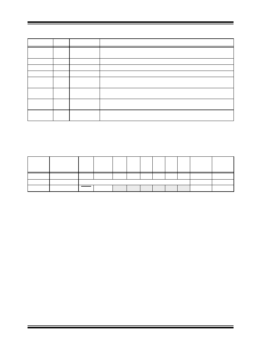
TABLE 4-3:
PORTB FUNCTIONS
TABLE 4-4:
SUMMARY OF REGISTERS ASSOCIATED WITH PORTB
Name
Bit#
Buffer
Function
RB0/INT
bit0
TTL/ST(1)
Input/output pin or external interrupt input. Internal software
programmable weak pull-up.
RB1
bit1
TTL
Input/output pin. Internal software programmable weak pull-up.
RB2
bit2
TTL
Input/output pin. Internal software programmable weak pull-up.
RB3
bit3
TTL
Input/output pin. Internal software programmable weak pull-up.
RB4
bit4
TTL
Input/output pin (with interrupt-on-change). Internal software programmable
weak pull-up.
RB5
bit5
TTL
Input/output pin (with interrupt-on-change). Internal software programmable
weak pull-up.
RB6
bit6
TTL/ST(2)
Input/output pin (with interrupt-on-change).
Internal software programmable weak pull-up. Serial programming clock.
RB7
bit7
TTL/ST(2)
Input/output pin (with interrupt-on-change).
Internal software programmable weak pull-up. Serial programming data.
Legend: TTL = TTL input, ST = Schmitt Trigger input
Note 1: This buffer is a Schmitt Trigger input when configured as the external interrupt.
2: This buffer is a Schmitt Trigger input when used in Serial Programming mode.
Address
Name
Bit 7
Bit 6
Bit 5
Bit 4
Bit 3
Bit 2
Bit 1
Bit 0
Value on:
POR,
BOR
Value on
all other
RESETS
06h, 106h
PORTB
RB7
RB6
RB5
RB4
RB3
RB2
RB1
RB0
xxxx xxxx
uuuu uuuu
86h, 186h
TRISB
PORTB Data Direction Register
1111 1111
81h, 181h
OPTION_REG
RBPU
INTEDG
T0CS
T0SE
PSA
PS2
PS1
PS0
1111 1111
Legend: x = unknown, u = unchanged. Shaded cells are not used by PORTB.
发布紧急采购,3分钟左右您将得到回复。
相关PDF资料
PIC18F24K20-I/SS
IC PIC MCU FLASH 8KX16 28SSOP
PIC16F77-E/ML
IC MCU FLASH 8KX14 A/D 44QFN
PIC16LF74T-I/ML
IC MCU FLASH 4KX14 A/D 44QFN
PIC16F723-I/MV
IC MCU 8BIT 7KB FLASH 28UQFN
PIC18F442T-I/ML
IC MCU FLASH 8KX16 EE A/D 44QFN
PIC18LF2439-I/SP
IC MCU FLASH 6KX16 EE A/D 28DIP
PIC16F687-I/ML
IC PIC MCU FLASH 2KX14 20QFN
PIC18LF2439-I/SO
IC MCU FLASH 6KX16 EE A/D 28SOIC
相关代理商/技术参数
PIC16F77T-I/PT
功能描述:8位微控制器 -MCU 14KB 368 RAM 33 I/O RoHS:否 制造商:Silicon Labs 核心:8051 处理器系列:C8051F39x 数据总线宽度:8 bit 最大时钟频率:50 MHz 程序存储器大小:16 KB 数据 RAM 大小:1 KB 片上 ADC:Yes 工作电源电压:1.8 V to 3.6 V 工作温度范围:- 40 C to + 105 C 封装 / 箱体:QFN-20 安装风格:SMD/SMT
PIC16F77T-I/PTG
功能描述:8位微控制器 -MCU 14KB 368 RAM 33 I/O RoHS:否 制造商:Silicon Labs 核心:8051 处理器系列:C8051F39x 数据总线宽度:8 bit 最大时钟频率:50 MHz 程序存储器大小:16 KB 数据 RAM 大小:1 KB 片上 ADC:Yes 工作电源电压:1.8 V to 3.6 V 工作温度范围:- 40 C to + 105 C 封装 / 箱体:QFN-20 安装风格:SMD/SMT
PIC16F77TIPT
制造商:MICROCHIP 功能描述:New
PIC16F785-E/ML
功能描述:8位微控制器 -MCU 3.5 KB 128 RAM 18I/O RoHS:否 制造商:Silicon Labs 核心:8051 处理器系列:C8051F39x 数据总线宽度:8 bit 最大时钟频率:50 MHz 程序存储器大小:16 KB 数据 RAM 大小:1 KB 片上 ADC:Yes 工作电源电压:1.8 V to 3.6 V 工作温度范围:- 40 C to + 105 C 封装 / 箱体:QFN-20 安装风格:SMD/SMT
PIC16F785-E/P
功能描述:8位微控制器 -MCU 14KB 368 RAM 33 I/O RoHS:否 制造商:Silicon Labs 核心:8051 处理器系列:C8051F39x 数据总线宽度:8 bit 最大时钟频率:50 MHz 程序存储器大小:16 KB 数据 RAM 大小:1 KB 片上 ADC:Yes 工作电源电压:1.8 V to 3.6 V 工作温度范围:- 40 C to + 105 C 封装 / 箱体:QFN-20 安装风格:SMD/SMT
PIC16F785-E/SO
功能描述:8位微控制器 -MCU 3.5KB FL 128R 18 I/O RoHS:否 制造商:Silicon Labs 核心:8051 处理器系列:C8051F39x 数据总线宽度:8 bit 最大时钟频率:50 MHz 程序存储器大小:16 KB 数据 RAM 大小:1 KB 片上 ADC:Yes 工作电源电压:1.8 V to 3.6 V 工作温度范围:- 40 C to + 105 C 封装 / 箱体:QFN-20 安装风格:SMD/SMT
PIC16F785-E/SS
功能描述:8位微控制器 -MCU 3.5KB FL 128R 18 I/O RoHS:否 制造商:Silicon Labs 核心:8051 处理器系列:C8051F39x 数据总线宽度:8 bit 最大时钟频率:50 MHz 程序存储器大小:16 KB 数据 RAM 大小:1 KB 片上 ADC:Yes 工作电源电压:1.8 V to 3.6 V 工作温度范围:- 40 C to + 105 C 封装 / 箱体:QFN-20 安装风格:SMD/SMT
PIC16F785-I/ML
功能描述:8位微控制器 -MCU 3.5 KB 128 RAM 18I/O RoHS:否 制造商:Silicon Labs 核心:8051 处理器系列:C8051F39x 数据总线宽度:8 bit 最大时钟频率:50 MHz 程序存储器大小:16 KB 数据 RAM 大小:1 KB 片上 ADC:Yes 工作电源电压:1.8 V to 3.6 V 工作温度范围:- 40 C to + 105 C 封装 / 箱体:QFN-20 安装风格:SMD/SMT